

Design review / IFC & DXF design loading
Bring design into the scene.
Review engineering designs in the same 3D workspace as your survey. Control layer visibility and opacity to inspect geometry in context.
Start with
Supported IFC or DXF files with understood units, design revision and coordinate alignment.
Create
Visible design layers alongside the recording for spatial review.
Why it matters
Reduce the distance between the captured site and the engineering information used to interpret it.
How ifc & dxf design loading works.
- 01
Select the design revision
Load the relevant IFC or DXF through the recording's design tools. Retain the file's provenance and revision.
- 02
Check coordinates and units
Verify placement against known references. Loading a design does not by itself establish a correct survey alignment.
- 03
Control the display
Toggle layers, adjust opacity and fit the view to the design. Inspect geometry and available feature information.
- 04
Review in context
Compare relevant features with the point cloud and supporting imagery. Record the viewpoint and the assumptions behind your interpretation.
Read the result in context
The AT300 illustration shows designs in their native coordinates with original cloud alignment unverified. It demonstrates loading, not a verified as-built compliance result.
Take the next step.
Terrain
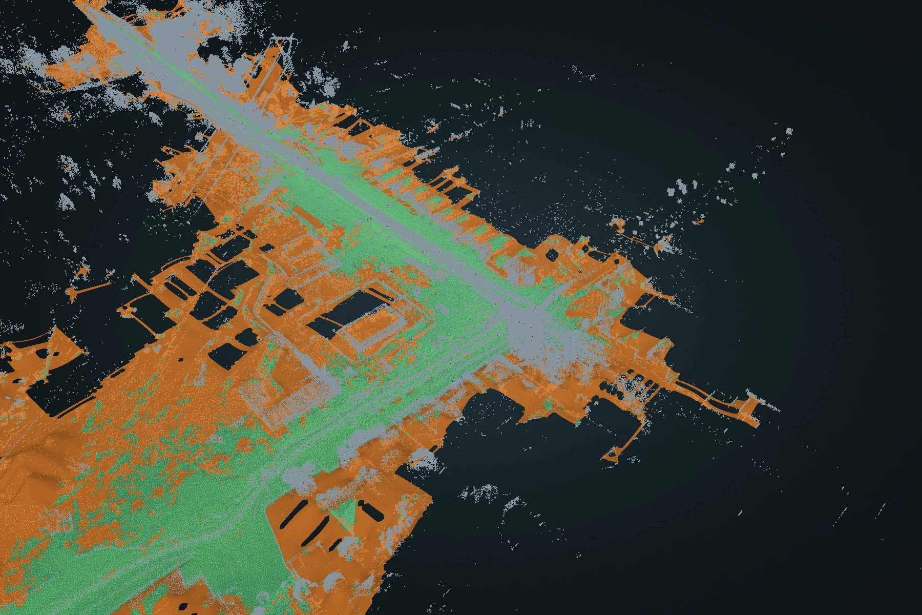
Terrain DEM
Turn a full point cloud into a ground-oriented elevation surface. Inspect fitted ground and reconstructed estimates, then carry the surface into CAD or GIS.
Explore Terrain DEM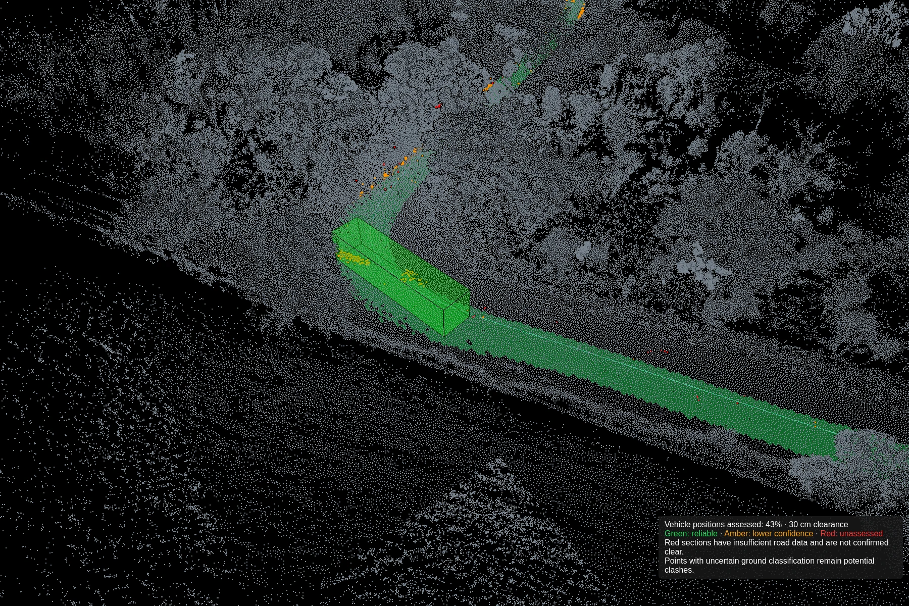
Clearance
Clash detection
Define vehicle dimensions, test the route against captured geometry and refine the path. Review road-surface support alongside potential intrusions.
Explore Clash detection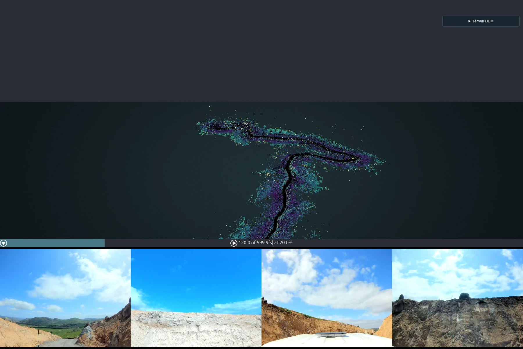
Visual context
360° imagery
Move through the recording by time and pose. Open any of the four camera images to inspect and save the full-resolution source image.
Explore 360° imagery